Construction drawing scales explained (with a scale chart)
What does 1/4" = 1'-0" mean?
It means a quarter inch on the drawing represents one foot on the building. One inch on the sheet is therefore 4 feet, and the drawing is 1/48 of full size, written as the ratio 1:48. Every scale works the same way: the note tells you how much real length one unit on paper stands for.
Architectural scales
Used on floor plans, elevations, sections and details. The ratio is 12 divided by the inches per foot; feet per inch is the real length one inch on the sheet stands for.
| Scale | Ratio | 1 inch on the sheet equals | Typical use |
|---|---|---|---|
| 1/16" = 1'-0" | 1:192 | 16 ft | Large building plans, key plans |
| 3/32" = 1'-0" | 1:128 | 10 ft 8 in | Large plans |
| 1/8" = 1'-0" | 1:96 | 8 ft | Commercial floor plans |
| 3/16" = 1'-0" | 1:64 | 5 ft 4 in | Floor plans |
| 1/4" = 1'-0" | 1:48 | 4 ft | Residential and enlarged floor plans, elevations |
| 3/8" = 1'-0" | 1:32 | 2 ft 8 in | Enlarged plans, sections |
| 1/2" = 1'-0" | 1:24 | 2 ft | Enlarged plans, wall sections |
| 3/4" = 1'-0" | 1:16 | 1 ft 4 in | Details |
| 1" = 1'-0" | 1:12 | 1 ft | Details |
| 1-1/2" = 1'-0" | 1:8 | 8 in | Details |
| 3" = 1'-0" | 1:4 | 4 in | Large-scale details |
Engineering (civil) scales
Used on site, civil and survey drawings. One inch equals a whole number of feet, so the ratio is that number times 12.
| Scale | Ratio | 1 inch on the sheet equals | Typical use |
|---|---|---|---|
| 1" = 10' | 1:120 | 10 ft | Site details, small sites |
| 1" = 20' | 1:240 | 20 ft | Site plans, grading, utilities |
| 1" = 30' | 1:360 | 30 ft | Site plans |
| 1" = 40' | 1:480 | 40 ft | Site and utility plans |
| 1" = 50' | 1:600 | 50 ft | Larger sites |
| 1" = 60' | 1:720 | 60 ft | Larger sites |
| 1" = 100' | 1:1,200 | 100 ft | Overall site and survey plans |
| 1" = 200' | 1:2,400 | 200 ft | Location and vicinity plans |
Metric scales
Metric drawings are dimensioned in millimetres and use plain ratios. Several are close to, but not the same as, an architectural scale; the last column shows the nearest one and how far apart they are.
| Scale | 10 mm on the sheet equals | Typical use | Nearest architectural scale |
|---|---|---|---|
| 1:5 | 50 mm | Large-scale details | None close |
| 1:10 | 100 mm | Details | 1" = 1'-0" is 1:12 |
| 1:20 | 200 mm | Details, sections | 1/2" = 1'-0" is 1:24 |
| 1:25 | 250 mm | Enlarged plans, sections | 1/2" = 1'-0" (1:24), 4% apart |
| 1:50 | 500 mm | Floor plans | 1/4" = 1'-0" (1:48), 4% apart |
| 1:75 | 750 mm | Floor plans | 3/16" = 1'-0" is 1:64 |
| 1:100 | 1 m | Floor plans, elevations | 1/8" = 1'-0" (1:96), 4% apart |
| 1:150 | 1.5 m | Large plans | 3/32" = 1'-0" is 1:128 |
| 1:200 | 2 m | Large plans, site | 1/16" = 1'-0" (1:192), 4% apart |
| 1:250 | 2.5 m | Site plans | 1" = 20' is 1:240 |
| 1:500 | 5 m | Site plans | 1" = 40' is 1:480 |
| 1:1000 | 10 m | Site and location plans | 1" = 80' would be 1:960 |
Close is not the same. 1:50 and 1/4" = 1'-0" differ by about 4% (50 against 48). Set a metric sheet to the imperial scale, or the reverse, and every length on it is 4% off, and every area about 8.5% off. It is a common and expensive mistake because the numbers look plausible.
How do you find the scale of a drawing?
Look for the scale note under each view's title, not only in the title block, because one sheet can hold views at different scales. Many sheets also have a graphic scale, a bar marked in feet or metres, which stays correct even if the sheet is printed smaller or larger. Then confirm with a dimension.
- View titles first. "FIRST FLOOR PLAN, SCALE: 1:50" applies to that view. A detail beside it may be 1:10.
- The title block. Often says a single scale, or "AS SHOWN", which means read each view's own note.
- The graphic scale. A marked bar. Because it is drawn, it shrinks or grows with the print, so it is the one scale that survives a reduced print.
- NTS. "Not to scale". Never measure an NTS view; take its numbers from its dimensions.
Why a scale note can be wrong
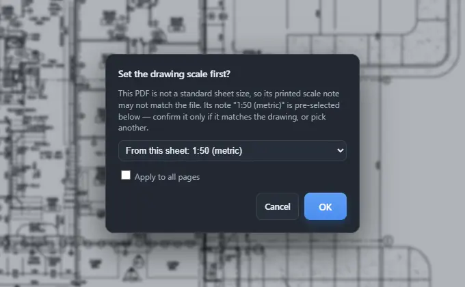
The note describes the drawing at its intended paper size. If the PDF was printed smaller, scanned, or resized, the note no longer matches the file. Sheet P0-1 of the clinic drawings in TRACEBUILD's demo set carries this warning beside its title block: "IF SHEET IS LESS THAN 28"X42", IT IS A REDUCED PRINT. SCALE REDUCED ACCORDINGLY." A 1/4" = 1'-0" plan printed at half size is effectively 1/8" = 1'-0".
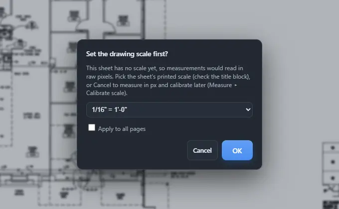
That is why TRACEBUILD, when it reads a scale note from a PDF that is not a standard sheet size, pre-selects the note but tells you it may not match the file, and why it shows the sheet's real-world size after you set a scale. On our demo sheet P2-1, setting 1:50 gave a sheet of 53.34 × 35.56 m, which is believable; setting 1/16" = 1'-0" by mistake gave 672 × 448 ft, which is not.
How to set the scale on a PDF plan, three ways
- From the sheet's scale note. TRACEBUILD reads the note when it can and pre-selects it. Confirm it only if it matches the drawing. Measure ▸ Scale the whole set does this for every sheet in a set and leaves sheets that already have a scale alone.
- From the standard list. Pick the printed scale from the presets: architectural from 1/16" to 3" = 1'-0", engineering from 1" = 10' to 1" = 200', and metric from 1:5 to 1:1000.
- From a known dimension. Use the calibrate tool: draw a line over the longest dimension you can trust, such as a grid dimension or an overall building dimension, and type its real length. The longer the line, the smaller the error.
How to check the scale before you measure
Measure a printed dimension you did not use to set the scale, and compare. A reading within a fraction of a percent means the scale is right. A reading that is double, half, or about 4% off points to a reduced print, the wrong scale family, or a metric and imperial mix-up.
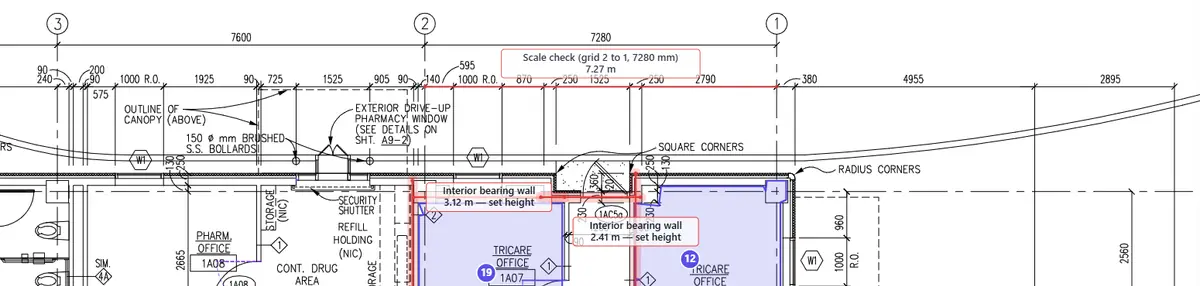
On drawing A2-2 of the demo set we set 1:50 from the note, then measured the bay between grid lines 2 and 1, dimensioned at 7280 mm. It read 7.27 m, 10 mm short, or 0.14%. That is a pass.
Check every sheet, not just the first. Sets mix scales between disciplines, and enlarged plans often sit on the same sheet as the main plan. Our step-by-step takeoff guide shows the check in context.
Common scale mistakes
- Trusting the note on a reduced print. Check the paper size against the sheet's intended size, or use the graphic scale.
- One scale for a whole sheet. Enlarged plans and details beside the main plan have their own scales.
- Measuring an NTS detail. Use its dimensions, not your ruler.
- Mixing metric and imperial. 1:50 is not 1/4" = 1'-0". The 4% difference compounds on areas.
- Calibrating from a short dimension. A small snapping error on a short line becomes a large scale error. Use the longest dimension you can.
- Skipping the check. One measured dimension takes seconds and catches every mistake above.
Related trades: sitework takeoff works on civil sheets drawn to engineering scales, and the flooring and concrete worked examples are measured on metric 1:50 sheets.